
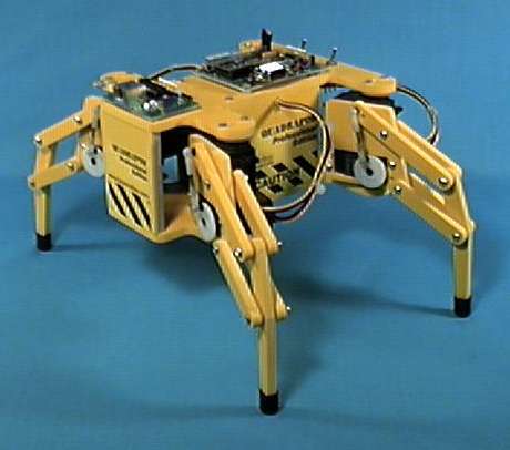
The Robot:
Quadrapod is my first Challenger series robot. The Challenger series projects are named appropriately. They are going to be very complex. Anyway, the frame for my original Challenger was built, but I didn't have any motors strong enough to operate it. I decided to start from scratch. The original frame for the Challenger would have used 9 motors. I re designed the frame and went with a different leg style that would use 12 servos, however I reduced it to 8 servos. This design is what has evolved into the curent Quadrapod. It's equivalent to a Lynxmotion Hexapod II with a pair of legs removed. The image above is a modified picture out of a catalog, showing what the frame will look like. The name Quadrapod is simple. Quad for four, and pod for foot. I also was thinking of the Macintosh Quadra at the time, and the "ra" fits right between the two nicely.
This is the final schematic which includes H-Bridges, reversers, and routing circuits that route pulses from a microcore (6 Nv nervous network). It takes 5 inputs (Stop, Go, Reverse, Right, and Left) and uses them to translate a 6 Nv Central Patern Generator to operate a 4 leg 8 motor walker (one motor to lift legs, the other to move them front and back). Revision 4 corects many previous problems and reduces the chip count. The schematic is large, so I've linked to it. Use back to return to this page. Also, note that even though this schematic shows H-Bridges, I will be using a latched operational amplifier motor driver. More complex, but it results in very nice features such as NO leg drift and self leg centering when the stop command is selected.
The basic operation of Quadrapod is simple. Speak into a Walkie-Talkie and it will understand the five commands Go, Reverse, Turn Right, Left Turn, and Stop. The control circuitry translates the 5 commands into the proper outputs for the routing circuits. There are several actions that occur, which include stand alone actions AND combining walking and turning. making 9 diferent gaits (Go, Reverse, Turn Right, Left Turn, Go-Turn Right, Go-Left Turn, Reverse-Turn Right, Reverse-Left Turn, Stop). Interestingly enough, I know how to make it into 17 gaits!!!! Long and short strides of each gait, and then stop. All I'd need to do is add a pair of resistors per motor and a switching circuit.
All major signals have easy access points. It makes upgrades EXTREMLY easy!!! I could easily build an infrared collision detector system and to add it would involve cutting a pair of wires out and adding 6 more! Not bad realy! I also intend to add a remote camera to it! I'll use a pair of servos for positioning the camera, and the control will have a 6 inch color LCD, the walkie talkie, and a remote control for positioning the camera. In addition to the remote control of the camera, I'd like to add a balance systen that biases the potentiometer in the servo to adjust the camera to reduce the bouncing of the robot as it walks! This will be based on an auto leveling system used on FMC Pea Harvesters (yes, I've run them things, and it's harder than it looks to drive 25 tons of steel down a gravel road)! The autoleveler uses a pair of pendulums. I'll only use one for reducing vertical motion. I may try other things (most people use gyroscopes, which are more acurate, but also more expensive and I think it requires a constant power source to spin the gyroscope.
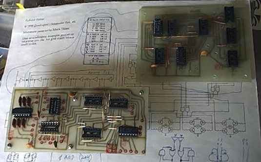
The PCB layouts are roughly drawn. I may redraw them later to clean them up. There is a scan of the actual PCB (2x normal size), and an actual size drawing. The drawings aren't necessarily to scale. Both PCB's are smaller than the drawings. I'll try redoing the drawings on computer, and then removing the old images. The PCB's were done using Radio Shack dry transfers on copper clad board.
Update! Ha, I finaly figured out how to use the Douglas Layout program for my Macintosh. Pretty nice!!! I'll be doing all my final layouts on the computer. I'll try to Follow certain design restraints to simplify producing it for other people who want to try it. These are pretty complex though, so I'll go and make them as compact as possible. This is not anything a beginer should even attempt. Get some major expirience first. My other smaller robots will be designed with ease of construction in mind. The Challenger series robots will be all out projects. If i can make it work, I'll add it.
Drawing of Routing circuit PCB
Douglas Layout image of Routing circuit PCB.
Drawing of Control circuit PCB
Douglas Layout image of Control circuit PCB (comming soon)
The motor drivers will be using a simplified version of the walk latch in the control circuitry, tied to an operational amplifier. I can cut out a pair of AND gates, since no stop line is required. That makes a reduction of one chip per driver pair (two per board, one board for each leg, two motors per leg). It will have a +5 volt and a -5 volt supply. The potentiometer in the servos will bias the comparitor. The latch will output two highs when both inputs are low, output highs and latch them when it recieves one low input, and when both signals comming in are high, the outputs are latched. The operational amplifier compares the inputs to the potentiometer on the servo. That produces three setable positions and a hold mode (latch).
I'll be posting diagrams for recreating the legs on the hexapod walker from lynxmotion (cheaper to build a hacked version than pay $375 for it!!!). I'll have details on servo modifications and mounting legs to them, as well as some various mechanical layouts to carry out different tasks.
The Controler:
The controler can be as simple as a Walkie Talkie. You speak into the microphone and it'll recognize the basic commands. More advanced options would be the video system. It consists of an RC transmitter and reciever. The contoller runs the servos on the robot. The autoleveler biases the servos to level the head (reduce bounce on the screen). The screen on the controler can be any LCD display. I'm using an NTSC 6 Inch color LCD. There is a transmitter and a camera on the robot, and a receiver and the screen on the controler. The screen I intend to use supports RGB overlay, meaning if I ever added a computer or microprocessor to the robot and or the controler, I can display text and graphics over the video image, kinda like on screen chanel indicators and volume level bars on TVs, but whatever I want it to be! Put simply, there is room for LOTS of expansion! I could add a proximity detector to the head, make a transmitter on the bot to send the data, have a computer in the controler convert it to a number or progress bar and display it on screen, and add cross hairs to indicate the location looked at. Of course, I don't plan on making it a priority, but it's nice to know it's possible.
| LinkExchange Member | Free Home Pages at XOOM | Free Home Pages at GeoCities |

|
The Richfiles is copyright © 1996-2000. All Rights Reserved.
