
Description:
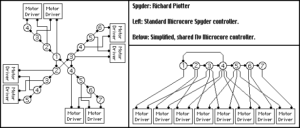
Spyder is an 8 motor, 4 leged walking robot. It uses a 16 Nv network with a 4 Nv loop, and four 3 Nv branches attached to each Nv of the loop. It features 4 legs, which can lift and drop, as well as extend and retract.
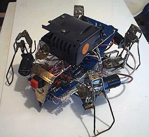
Side View of Spyder
Electronics:
I planed on building two controllers for Spyder. The controller is a fairly uncommon, but standard 16 Nv "Branched microcore", which is essentialy a 4 Nv Microcore with a string of Nvs on each of the 4 Nv corners. The branches do not loop (only the central microcore). This makes biasing very easy by adjusting the first or all the Nvs in the branch. The second method is something I came up during a class in colege. It's a 7 neuron setup with a 3 neuron branch on a 4 Nv loop. It'd work, but biasing the network is far more difficult.
The large circles are each Nv, and the black circles indicate excitatory inputs. A filled triangle (point facing the line) would represent an inhibitory input. Spyder uses no inhibitory inputs, making the circuit rather simple. The following image shows the layouts of each the the two networks mentioned above.
Turning can be accompllished in two ways. It is possible to incorporate a bicore based head to operate several MUXes to control the routing of the signals. That can make it phototropic in 4 directions. It would seek light in a "stair step" walking pattern. The second means it can seek light would be by motor biasing. I will more than likely use this method. Adjusting the Nv timing can change the leg swing. I will also add a heavy turn and a reverse function. by reversing 4 of the 8 motors, reversing can be acomplished. Killing a single motor on either side appears to provide a usefuly decent turn radius! The mechanical design is quite versatile!
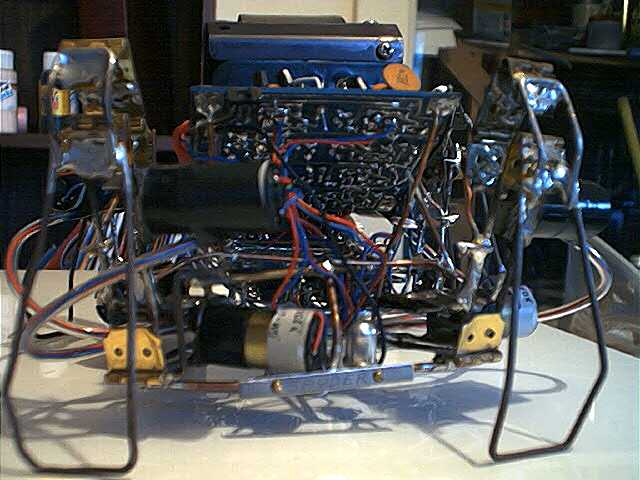
The motors are driven by 6 transistor H-Bridges, one for each of the 8 motors. These happened to be "smokable" H-Bridges, so I had to create a bridge between the two. I used a Z-Bridge, which prevents the condition that causes the motors to smoke. It also provides a conveniend enable line that can electronicly disable the motors. I designed the board with a jumper so I can short it when I need no electronic control, and pull the jumper and connect the signal line if I upgrade it to incorporate a motor enable/disable circuit. There is also a power switch that enables or disables power to only the H-Bridge board (for a manual motor kill). There is also a mercury (Hg) switch that disables power to the motor drivers if the bot is held upside down. Saves power when the robot is tipped or being moved. The following link opens a Quicktime video of Spyder 's orientation sensing working...
Spyder's Orientation Sensing - 1.4 MB
Mechanics:
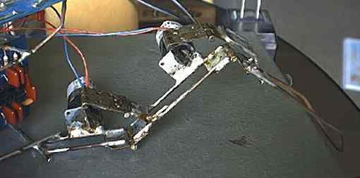
The robot has 4 legs that can lift up and down and extend in and out. the gait would be even better with 4 more motors to rotate the legs, but that'd be pretty expensive. 8 motors was $136! to walk it lifts the legs on opposite corners, moves them out, drops them, and then pulls itself forward. This occurs in a 180 degree alternation with the other pair of opposing motors. The robot walks quite well. The above mentioned leg motion results in a tiny zig zag walking gait. It pulls itself to the front and left, to the front and right and so on. As the thrusting legs pull back, propelling the bot forward, the other pair lift in the air and move forward again, preparing for the next step. This gait is shown clearly in the link to the Quicktime video below.
Spyder's Walking Gait Video - 6.1 MB
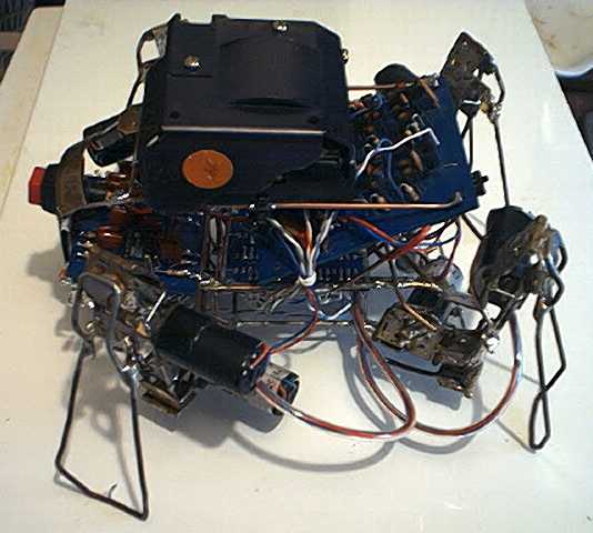
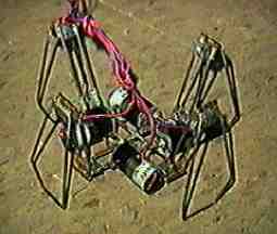
The motors are attached to the legs via hinge assemblys. The leg mounts to it's pivot with one hinge. The motor is mounted to the same point the pivot is on. The two other hinges form a sort of "lever" drive. This places the most force of the robot's weight on the hinge instead of all on the motor shaft. This likely helps to reduce motor wear. The following image shows a leg up close. It should be clear enough to understand how it works. All the joints move freely, and the motors have the torque to move the robot around very well.
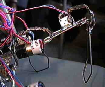
Close up of Spyder's Leg Extended.
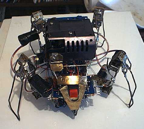
Spyder features a few asthetic additions too. Spyder uses all hand made boards with a blue color. That was what I started with, and kept the color scheme cause it was unusual and looked good. Spyder's battery case is concealed by a metal shield that hinges forward. Spyder uses 4 AA batteries.
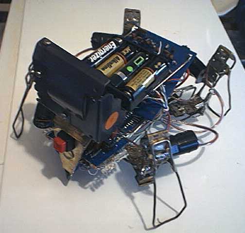
I also engravd a small metal nameplate. I soon found a larger one I liked better and engraved it. I now have a pair of engraved nameplates on Spyder. One is mounted to the front top above the power switch. The other is mounted in the rear, license plate style.
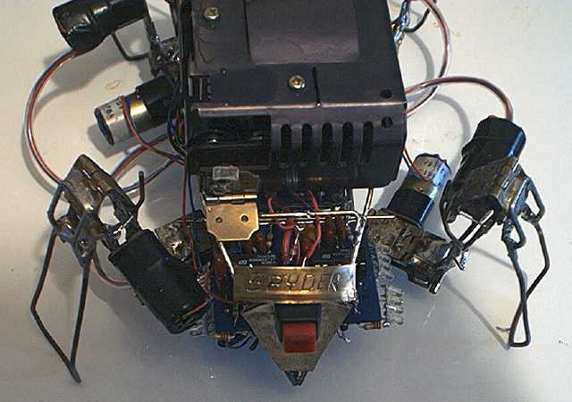
Spyder's License Plate
History:
Spyder was started a LONG time ago. Early February 1999 to be exact! For over 2 months it sat around with only the 4 lower motors attached and no motor to leg linkups.
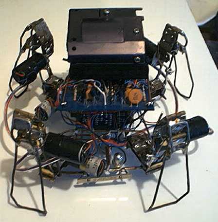
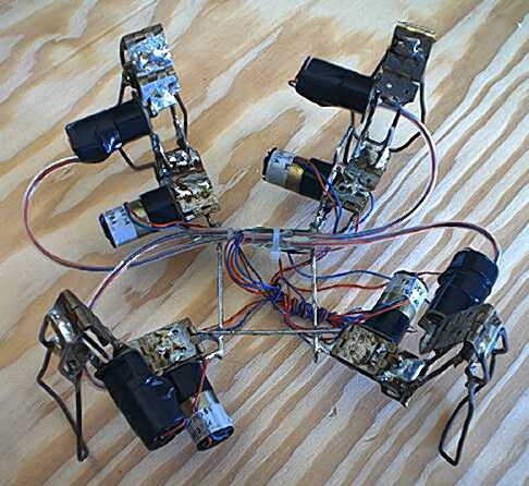
Now it is mechanicaly complete, but you can also see the base was redesigned. it was infact redone 3 times! The image below is the final frame layout before electronics werre added.
Construction on Syder would halt for months at a time, depending on how busy I was with other things, such as school. The longest delay was when I realized the H-bridges would "smoke" if the Nv net saturated development halted. It took a lot of ambition to get started again. Once I restarted, the frame took it's final shape. Another delay, due to lack of electronic parts resulted in another multi-month delay. I finaly recieved the parts, but was too busy with my final months of colege. Then it was moving. Finaly, at the end of my last summer vacation, I have gotten all the parts together, assembled, tested, and actualy finished Spyder! Seeing Spyder walk for the first time in 1-3/4 years was a great feeling!
| LinkExchange Member | Free Home Pages at XOOM | Free Home Pages at GeoCities |

|
The Richfiles is copyright © 1996-2000. All Rights Reserved.
