
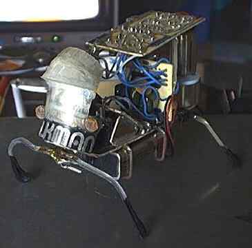
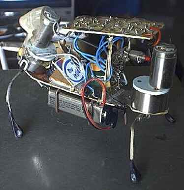
Original Walkman. (before accident)
Description
The first robot I built is a 4 leg/2 motor walker. It uses a 4 Nv microcore (Nv stands for Nervous network). The microcore is a loop of Nv units that cycle pulses through to operate a device. Mark Tilden designed the microcore using a 74HC14 schmitt triggered inverter, a resistor, and a capacitor.
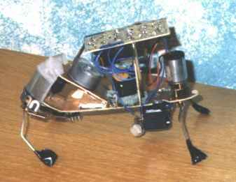
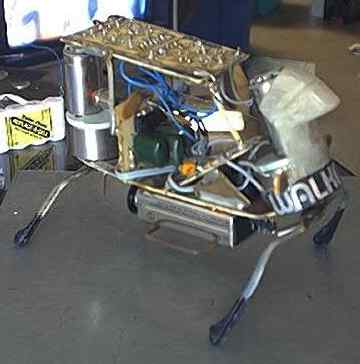
Walkman Was originally very different than it is now. The original design was large, bulky, and the two motors ended up getting stripped because the gears were too weak. I later used a motor from the eject mechanism of a camcorder and a walkman motor with a hand built gearbox. Walkman (as well as my three solar robots and BORIS, my muscle wire robot) were used on an episode of Algo's FACTory. (Sunday mornings at 9:30 on FOX, at least in my area). It's a children's educational show. Walkman accidentally walked itself off of a table and the front gearbox (the one I built) was destroyed. I replaced it and the back motor (so they matched) with high quality gear motors. They are great!!! I also added eyes just after first getting it to work. When it's dark, it "sleeps." One of the most notable features is actually the "head" made from a diffraction grating (like on those action baseball cards where you tilt it and the image changes). It's there for appearance and to act as a barrier between the eyes, (though they don't do much of anything except cause the robot to sleep).
Mechanics
2 motor walkers are unique in that mechanical design is almost more important than the electronics. The robot moves by "falling" forward. It lifts it's front legs, pushes with it's back. An ideal 2 motor walker should have it's center of gravity as close to the point where two imaginary lines would cross if each line attached to the feet of the legs diagonally apart. To tell if a 2 motor walker has a proper center of gravity, tilt the front legs and see if it can tip from front to back. If it stays where you tip it, it's pretty good. The front legs should be tipped up at approximately 30 degrees. The legs shapes you need to play with. Try different things. If you use servos, you can get a 4 point horn and bend the legs into a triangle shape at the center. attach the points to three of the points on the horn. The 4th point can have a spring attached to bias and help center the legs, or to operate stop switches. The servo's built in potentiometer can be used to bias a microcore or if you use a micro controller, the servo does not need modification.
Two motor walkers can't really turn efficiently. you can bias the rear legs to make it turn a wide radius, but it's really not too feasible for a beginner. I may refit my walker to do it or do another 2 motor walker. I do plan on another 2 motor walker using off the shelf parts. The instructions will be found on the main robotics page.
Electronics
The Nervous Network: My 2 motor walker uses a nervous network. Nervous networks are very similar to Neural networks, however there are important differences. Nervous networks, in the most basic sense, imitate neurons that are responsible for reflexes. Each neuron is a single inverter. The inverter MUST have a schmitt trigger. A schmitt trigger allows a signal to fluctuate a little bit without rapid triggering of the output. There are two thresholds, a high and a low. if the input is low and rises, the output won't go low until the input hit's the high threshold. if the input goes back below the high threshold, the output won't change, but if it goes far low to the low threshold, then the output will go back to high. This allows leeway for the input. It's a very interesting system
The 74HC14 hex schmitt inverter is the most popular inverter for use in nervous networks. They can be chained, or looped. A loop of nervous networks are called a microcore. the inverters are joined by a capacitor, usually between .1µf and .3µf (I like using .22µf capacitors). A resistor is attached to the inputs. 1 Mega Ohm (M˝) is a good value to use with .22µf capacitors. It's easier to alter the value of the resistors than the caps. You can also use the servo pots to bias the microcore. attach the two outside pins to the inputs of the neurons that drive that servo. Attach the center lead through a resistor to adjust the value properly, and then it to ground. if you attach the microcore straight with fixed resistors, than a fixed resistor on the inputs and to ground. The outputs of the microcore can go to LEDs, drivers, or other devices.
The "odd" microcore I accidentally built. It's a mistake in my PCB, but it works:
PCB layout of the odd 4Nv microcore (note the place the output attaches to)
The following is a traditional microcore:
Schematic of the traditional 4Nv microcore
PCB layout of the traditional 4Nv microcore
The Nervous network and Microcore are patented my Mark Tilden. It's a really interesting device. It has many uses!
The Motor drivers: I used an H-Bridge to drive the motors on this particular robot. The H-Bridge is a rather ingenious design. I don't know who invented it, but it's an EXCELLENT design. It uses 4 transistors to route electricity through a motor. There are two inputs. One attaches to one pair of transistors and the other to the other pair. The schematic resembles an "H" (hence the name). When both are on or both off, the transistor with the polarity matching the input activates. In this case, it's equivalent to connecting both wires of the motor to (+) or (-) on the battery. It won't work. If one OR the other , but NOT both, are on, then one side of the motor is routed to (+) or to (-) and the other side remains at it's former polarity. This creates a (+) on one side and a (-) on the other, or vise versa, depending on which line is active. This makes the motor turn one way or the other. By attaching the microcore or a micro controller to the inputs, you can control a motor. This requires a DC motor, which can be a hacked servo. remove the electronics, but leave the pot and motor (some servos use the pot as the axle for the main gear (one I had did anyway). Attach the driver outputs straight to the motor and the pot can be attached to the microcore (optionally).
PCB layout of the dual 4 transistor H-Bridge
Walking
The microcore is attached to the H-Bridge driver. There are four neurons, and 2 motors (a neuron for each direction the motors can turn). The sequence I use is as follows:
Front Clockwise, Rear Counter Clockwise, Front Counter Clockwise, and Rear Clockwise
The front leg lifts, the rear leg pushes forward, the front legs shift balance and fall forward and the rear legs push again. It continues this in a loop and creates forward motion. To reverse, you can reverse the rear motor, however this robot does not have that feature.
That's pretty much everything I've got on my first robot, Walkman. I've not included instructions for building it, since there are lots of custom and limited quantity parts. It can be built by using servos or ither motors. Just make sure the front motor is at approximately a 30 degree angle.
For a video of Walkman, you can check out this Quicktime video. It's a nice side view of Walkman walking, as viewed by another robot with a camera mounted on it's side. It follows Walkman next to it, slightly slower, so you see Walkman walking accross the screen, but you get more footage cause the cambot follows it. Cambot is just a plastic Robotix kit that I threw together. Next thing you know, I'll probably start setting up a model trains with the camera to follow it in panoramic views! :)
Walkman & Photopopper Video-253 K
The Richfiles is copyright © 1996-2016. All Rights Reserved.
