
NOTE: The SPinTerface design here is known to lose voltage when the batteries get low. If you want an easier way to build it, add a small silicon diode from the Activation pin on the connector to the 5v+ pins. A 1µf capacitor between 5v+ and ground and between Batt+ and ground is sufficient to REPLACE the voltage regulator. This might not give perfect regulatoion, but it's far more reliable with lower batteries.
New schematics should be up soon showing this method.
If you're here, then you have probably heard of the SF Expander, designed by Mel Tsai. If you haven't, you can check out his device at his web page.
I have taken his SF Expander a step further. I have built the power supply directly into the TI-85 and created a small port that contains a duplicate serial port, 5v+ regulated power supply, and a simple power activation system that makes sure power isn't wasted while nothing is connected to the port, and makes sure all conections to peripherals are made before power is turned on.
The expander's chips are built into simple cartriges that plug into a small 10-pin connector on the bottom or bottom side of the calculator. Other peripherals can be attached and run off the calculators own power.
I will first describe the building of the S/P Interface (Serial/Powered) that I have come to call the SPinTerface Port. I will then show how to build the cartriges. I'll also show how to build a battery expander that allows you to connect a AA battery case to the TI-Calcs (This increases power, life, and also is cheaper because the AA batteries are usualy cheaper than AAA's).
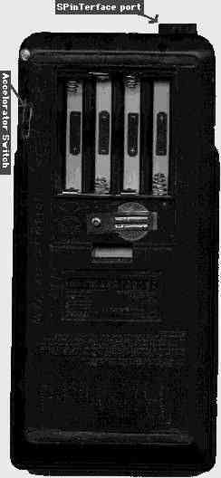
The SPinTerface Port:
The first thing you should note is that the wires can get very STUFFED in side your calculator. I do NOT recomend this upgrade unless you feel confident of your abilities. You NEED to know how to solder well, use a sharp utility knife, and you need to be able to follow schematics and instructions, etc. You should also note that I don't hold any responsibility if you accidentaly screw something up.
Before you begin, you should collect all the parts for the SPinTerface. You'll need a small, 10-pin female connector with two rows of 5 pins, a low dropout voltage regulator like the LM2931Z-5.0 or the LP2954 IS, both from National Semiconductor, a .1µf ceramic disk capacitor, a 10µf electrolytic capacitor and some thin bus wire. You'll need super glue for the parts mountings and for holding down the wires.
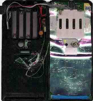
To begin, make a back up your calculator's memory (use a group file if you aren't using z-shell. If you are, then make a backup file). Proceed by opening it up. There are three screws, one inside the battery case holding the backup battery in, and two just below the battery case. Once these are removed, you can pull the case open by prying on the bottom and shifting it back and forth till the back pops off. (If you have turboed your TI-85, and it has a switch to select speeds, then you will want to take care that you don't harm the wires (It is best if the wires are long enough to lay both sections flat on a table). Once it is open you can begin modifying the case.
Modifying the case
You'll see that on the back case at the bottom where the link port is, there is a plastic piece that keeps the link plug from shifting. From the bottom, on the left side of the link port mount, you'll see that a plastic opening reaches to the very back of the case. You need to cut the other side the same way. This is to allow the wires to pass through. Then cut out a place along the bottom or the side of the back case for the 10-pin connector. You need to make sure there is room and you may also have to cut into the angled edge. The only place on the front piece of the calculator that needs to be cut is the edge just above the connector. It can't be deep, only the edge, so it's flush with the connector itself.
Components
The first step in building a circuit is to have the design ready, so I'll put up a schematic of the entire SPinTerface.
Now that you have a schematic to follow, you should go ahead and install the voltage regulator. place it so the numbers face up and the pins point to the bottom of the calculator. The regulator should be glued down. Now you should close the case to determine if everything fits right. If the case wont close all the way, then you need to check if anything is in the way. My calculator already had an accelerator switch installed previously, and I wasn't able to move the voltage regulator as far up as I would have liked. I had the problem, later on, of having dificulty with the wires. The case was very dificult to close. I eventualy got it closed properly, but you should make sure to completely avoid this. Simply make sure the voltage regulator's edge is not passed the bottom edge of the battery case. This will make things much easier.
Now you will want to get the two capacitors ready. Simply solder them together in paralel. Those, in turn, are soldered onto the "in" and "ground" pins on the regulator (you MUST make sure the (-) lead of the electrolytic capacitor connects to the "ground" pin).
Wiring
You will want to have the connector ready for the next steps. You will need to correctly position it in order to measure wires, but don't glue it to the case yet. If you do, it will be almost imposible to do all those tiny solder connections in the small spaces inside the calculator. Please read the following section a few times before you actualy do anything. I messed the wiring up twice! It's extremely easy to switch a wire or two.
Now solder a wire onto the "in" pin and run it below the battery case, through the link mounting that you cut out and to the other side where it will reach the hole you cut for the port. Cut two more wires of similar length and solder one to the "out" pin on the regulator and the other to the "ground" pin. The one on the out pin is the 5v+ line and the other, of course, is ground. Solder the 5v+ wire to the last two pins on the connector and the ground to the second last two pins. The two center pins on the connector are to turn the regulator on and off. Solder the wire from the "in" pin on the regulator to the top pin in the center row. The bottom pin will connect to the unregulated power supply. Cut a wire that reaches from the top center pin on the connector to the positive battery spring terminal and solder it in. You will want a little bit of slack, but not too much. The wire needs to reach all the way, so that the calculator can still be opened up easily. Run another wire from the "ground" pin on the regulator to reach the negative battery spring terminal. Now cut three more wires. They need to reach from the link port all the way to the first three pins of the connector. One wire should be connected to the end pin of the link port jack. This is the data line. Another connects to the left middle pin of the jack. This is the clock signal. The third wire connects to the bottom right pin on the link port. This is the signal ground. The signal ground should be soldered onto the second first row on the bottom pin. Solder the clock wire to the bottom pin of the very first row, beside the ground pin. The top pin of the first row should be connected to the data line.
Now you can super glue all loose wires and the SPinTerface port connector. Only put super glue on the sides and bottom of the connector, or it will glue the front of the case to it. The last construction step is to put a small piece of plastic into the pin with no connection (The top pin in the second first row). If you take apart old computers or hard drives you may find a plastic block designed just for these female connectors. Otherwise, use a knife to cut a sliver of plastic (I used white, so it was easy to see) and push it into the hole for the non-connected pin. You can now cut it so it's flush with the surface.
Troubleshooting
Put the two pieces of the case together and see if it fits. If it absolutely won't go together, then look for stray wires and glue them down. If a wire is pinched between the cases, pull it out of the way. Once you have the case closed, put in the batteries. To test it you need a few pins or a plug that will plug into the connector and a small volt meter. Connect the two pins of the middle row together. This activates the voltage regulator. Use the volt meter to test the voltage between the ground pins (second last row) and the 5v+ pins (last row). Make sure the negative wire of the meter is on the ground pins. If it shows somewhere close to 5 volts, you're fine. If it is closer to 5.5 or 6 volts, then recheck wiring and the voltage regulator. If it is a negative value, you may have crossed some wires. Recheck the wiring. Now turn the calculator on. If it won't turn on and you checked the contrast, then make sure there aren't any shorts, solder balls, or anything else touching the wires on the circuit board. Check the voltage between the data and the signal ground and then the clock and signal ground. Both should be very close to 5 volts (It's OK if they are higher. This is normal) but not lower. If they are lower or almost or at zero, then check your wiring.
You will need to check the old link port too. The best way to do this is to see if your data backup you made before starting the project will transfer back. If you get errors and the cable is all the way in, then recheck everything.
Z-Shell
If you don't use z-shell yet, you MUST install it or you've just wasted an hour or two. For those of you who don't use it, it lets you run assembly language programs on the TI-85. Assembly language can run the link port directly, and you need a driver to run the link port for some devices you attach to the SPinTerface. The best example of this that I can think of is Mel Tsai's SF Expander. The expander is a 512k or 1 Meg serial flash chip that uses a serial interface. This interface is different than the TI link port interface. The driver changes how the link port runs so it can interface properly with the chip. Z-shell can only be transfered with a memory backup. You can get the backup off the internet at ticalc.org.
You're DONE!!!
If you are done wiring the SPinTerface port to the regulator, power source, and the link port, and if it works fine, and if you now have z-shell and all the drivers for any special devices you need to attach to it, such as the SF Expander, then you should be very, very proud. You are DONE!!!
What's it for?
I originaly created this new type of port for the TI-85 primarilty for The SF Expander. I wanted it to be expandible, but I didn't feel like having to worry about a box on a wire always hanging around and I didn't want to deal with an extra battery. I have come up with a design for tiny cartriges that plug into this port. They can contain anything from speakers to memory to even a small LED (Believe me, I tried it. Use the right type of resistor though)! To learn how to create these cartriges, click HERE for instructions on cartrige assembly...
Do you have questions? got to the SPinTerface FAQs Page or e-mail me if your question remains un answered. This port is a great opportunity to add peripherals and stuff to the TI-85. If you have any cool ideas or designs, let me know about them! Hey, let me know if this thing is becoming popular or not! Why not tell me if you installed one. I'd love to know what you TI-85 enthusiasts think of it.
| LinkExchange Member | Free Home Pages at XOOM | Free Home Pages at GeoCities |

|
The Richfiles is copyright © 1996-2000. All Rights Reserved.
